Draw Mode
| Render Sprites | Renders Sprites at the location of each vertex instead of the polygons of a geometry. | |
 | Render Lines | Renders customizable Lines along the edges of the polygons of a geometry. |
 | Render Wireframe | Renders Lines along the edges of the polygons of a geometry with low performance impact. |
 | Render Path | Renders a list of vertices as a single customizable Path. |
 | Render Solid | Renders the geometry as Solid Polygons. |
The Render Mode Nodes are Aliases of the Material Node. They change they way the following objects will be rendered. The Material Node has other options that are documented on the respective pages (see table below for more information).
General
The Material Node controls the appearance of the surface of each rendered Object placed as a child in the Hierarchy. It consists of several options that can be added to its list of properties to overwrite the according options. The options are available under Material Node's Tabs that are represented by the button bar on top of the Material Definition in the Property Editor.
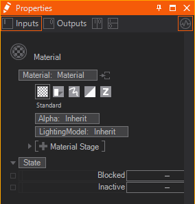
Generally these tabs exist:
| Standard | affects the overall transparency | |
|---|---|---|---|
changes how light affects the color of a surface | |||
adds textures and material stages that change the shading | |||
| Shadow Options | changes the shadow related behavior | |
| Drawing Style | applies a draw mode for geometries (lines, solid, sprites etc.) | |
| Blending | changes the write mode to specified color channels | |
adjusts the blending of geometries onto the background | |||
| Testing | applies a custom test against the object's alpha | |
defines a custom occlusion test for the geometry |


To show the options of a tab simply click on the according button. You can insert options by clicking on the Property Group's entry and choosing the wanted options from the dropdown.
All options that you do not adjust in a Material node are inherited by the Default Material or the Material node in front.
Icon and Decoration
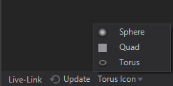
In general the Icon rendering can be changed by switching between Sphere, Quad and Torus at the bottom of the Properties Editor or via .
Based on the Property Groups that are used inside a Material Node the Icon may change.
| Rendered Preview | if only Property Group's in the Standard or Shadow Options tab are used. |
|---|---|---|
| Rendered Preview with light blue decoration | if Property Group's in the Standard or Shadow Options tab are used together with any other Option like a certain Draw Mode or a certain Blending |
| Dedicated Option Icon | every Material Option has it's own dedicated Icon, that is shown whenever no other Property Group in any other tab is used. |


Extraction
Material Definition
A Material node is a Hierarchy Node by nature. But it can serve as a Material Provider as well. This is useful whenever you want to use the same material in different locations of your hierarchy or once you have Hierarchy Nodes that need more materials than one applied to it (e.g. the Particle System Node). The below image shows both a Material Node and an extracted Material Node Provider together with a receiving Material Node.
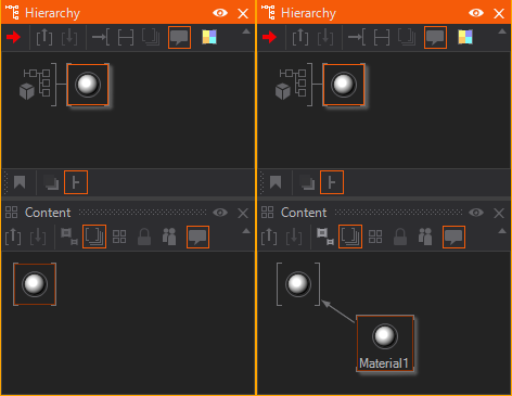
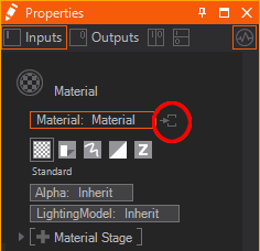
You can either place the Material node in the Content Editor to create an unbound Material Provider node. Or you can use the extract button  on any node that hosts a Material Definition to extract it to a provider that can be re-used on other nodes.
Material Options
Since a Material consists of several options sometimes you want to extract some of them to a seperate Hierarchy Node. This way you can apply single Material Options to other parts of the Hierarchy Tree when already added to the Material. Just use the extract buttons next to the Material Options.
Render Modes
Ventuz provides several Modes to render objects to the screen. This can be mainly understood as how the renderer interprets the polygons of a geometry. The following render modes are available.
Render Solid
Render Solid is the default draw mode and lets you draw all polygon's faces. You can change the Culling of the front- and backfaces.
Render Sprites
The Render Sprites mode will render a texture at the position of each vertex of an object.
The vertices can be Culled - either Frontfaces, Backfaces or no faces can be excluded from the rendering.
The uniform Scale and the Aspect can be changed with the according properties as well. The aspect is calculated with the formula 2x. So if you need an Aspect of 16:9 you need to type 0.83 (which is log2(16/9)). If you need an aspect of 9:16 it simply is -0.83.
The Scaling flag changes whether or not the sprites should scale with the distance to the camera. If ZNearFadeoutEnable is enabled the sprites fade out the alpha if they come near the camera, the threshold can be set with ZNearFadeout.
PointSpriteUV defines to which UV set the UV's generated for the sprites are applied. Setting it to UV1 for example allows to use a texture for the sprites but still use another texture on the geometry's original UV0 set.
If wanted, the Sprites can be Offset in X and Y position on the screen from the original vertex' position. If EnableRotation is turned on the Rotation changes the 2D rotation of the sprites.
You can change the direction of Billboarding:
- Toward Camera: Align the sprites towards the camera.
- Along Forward: Rotate along the Forward Vector of the particle.
- Along Speed: Rotate along the Velocity of the particle. Normally this only exists after a simulation.
- Along Direction: Use Billboard Reference to create a Rotation Vector to which the particles will be aligned.
- Toward Position: Rotate towards a Position given through the Billboard Reference.
- Toward Axis: Rotates towards an Axis defined in the Billboard Reference
- Normals Toward Position: Only changes the normals' directions towards a position but leaves the rotation of the particle as it is.
- Normals Toward Axis: Only changes the normals' directions towards an axis but leaves the rotation of the particle as it is.
- Invert: Can be used to invert the resulting vector. Only applies to Toward Position and Toward Axis billboarding.
- Update Normal: When directions are changed in any modifiers in the particle system the sprites normals need to be updated during the rendering. Turn this off if you want to keep the original direction of the particles' normals.
The Billboard Reference uses a Transformation property group. Alignment enables you to choose which axes are locked to the billboarding. The VR option locks the X and Y axes and is useful for cameras that have an animated roll.
Render Lines
The Render Lines mode will render customizable lines along the edges of the polygons.
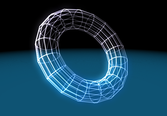
This mode has a set of Culling modes available to remove certain edges from the rendering:
- Show All: Renders all visible edges.
- Show Rim: Only renders the edges that appear to be the outermost ones from the current perspective.
- Show Front: Only renders the edges that are facing towards the camera.
- Show Back: Only renders the edges that are facing away from the camera.
- Show Front+Rim, Back+Rim, Front+Back: Combinations of the according modes.
- Remove Flat Tesselation: Removes all edges between two faces with the same normals.
Width changes the thickness of the lines while WidthMode changes how the width is affected by perspective. Unperspective keeps the lines at a constant width on the screen. Perspective Unscaled applies the perspective distortion to the lines but does not use the scaling from the Axis Nodes in front. Perspective Scaled does both - regarding the perspective and all axes. Planar Optimization can be used to prevent the distortion from the projection - that is appearing in high aspect ratio or high field of view setups. This is useful for planar objects rendered as lines but should be disabled for 3-dimensional objects in order to keep its spatial impression.
If in Unperspective node the rendered lines will drop shadows as if they were in Perspective Scaled mode, because shadows will not work with Unperspective lines.
LengthRel and LengthAbs change the length of the lines. Relative length is the percentage to the distance between the endpoints of the edge. Absolute will add an additional length independent from this distance. LengthFromWidth changes the length proportionally to the lines' width.
CapLength will add a cap of the given length with UVs to the end of each line.
The UVs used by the Material Stages can be changed with the UV0 and UV1 dropdowns:
- Original uses the UV set of the geometry.
- Relative applies UVs stretched from start to end of each line.
- Absolute applies UVs of same proportions to each line, so the UVs are not stretched on lines of different length.
- Stretched will use the center pixels of the texture along the line and applies its two halves to the caps of the lines.
Example:
| Relative UVs Each edge shows three dashes. The center edge is longer, so the dashes are longer. | 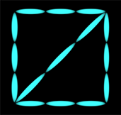
|
| Absolute UVs Each dash is the same size. The center edge is longer, so there are more dashes. | 
|
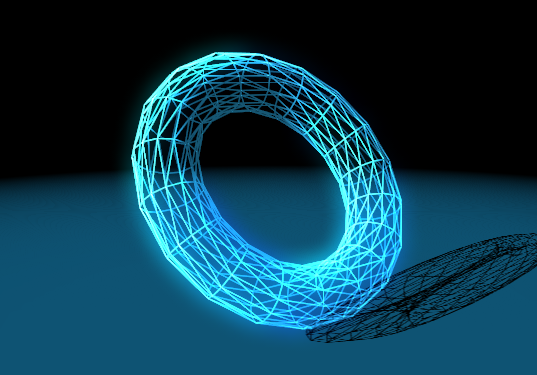
Render Wireframe
The Render Wireframe mode renders the edges of the polygon using a fill mode defined by DirectX11. This results in a very fast line rendering with very little options. You can only turn Culling for front- and backfaces on and change the Antialiasing of the lines.
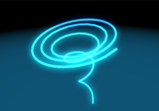
Render Path
The Render Path mode is a specific mode that makes sense with a list of vertices only - instead of a set of polygons. See the Path Renderer for more details on how to render paths. Using the Path mode instead of the Lines mode will result in a much smoother result, as the renderer can assume that not more than two edges are ending at one vertex - thus applying Caps to the edges' ends is not necessary anymore. You can turn on wireframe rendering in the Renderer's options to see the exact difference between both modes.
Width changes the thickness of the path while WidthMode changes how the width is affected by perspective. Unperspective keeps the lines at a constant width on the screen. Perspective Unscaled applies the perspective distortion to the lines but does not use the scaling from the Axis Nodes in front. Perspective Scaled does both - regarding the perspective and all axes. Planar Optimization can be used to prevent the distortion from the projection - that is appearing in high aspect ratio or high field of view setups. This is useful for planar objects rendered as lines but should be disabled for 3-dimensional objects in order to keep its spatial impression.
If in Unperspective node the rendered paths will drop shadows as if they were in Perspective Scaled mode, because shadows will not work with Unperspective paths.
The UVs that should be used by the Material Stages can be changed with the UV0 and UV1 dropdowns: Original uses the UV set of the geometry, Relative applies UVs from the beginning of the path to the end and along its width.