Table of Contents
- Ventuz Configuration
- Machine Configuration
- Introduction to the Video Engine
- AV Configuration
- Render Setup Editor
- Warping and Soft-Edging
Render Setup Editor
The Render Setup Editor is part of the Ventuz Configuration and is used to create an XML configuration for complex display walls. The content for such display walls may come from a single or from multiple Ventuz machines. Generally speaking, the Render Setup Editor is used to solve following problem: Display Ventuz content correctly on an arbitrarily complex display wall built up of N displays connected to M machines.
In other words, the Render Setup is the link between the design canvas and the actual physical output of the graphic board. Be it a simple bezel compensation or overlap, to a 4x1 stripe of LED panels that is fed from one output, to a complex display wall.
To span the render output across multiple displays, a multi-display group has to be created. (AMD Eyefinity / Nvidia Mosaic)
User Interface
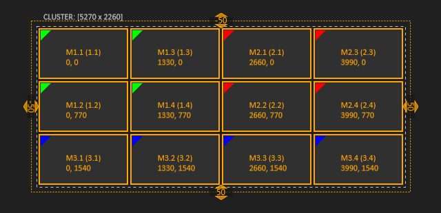
The editor basically consists of three parts: the Toolbar on top with some edit commands, the Display Editor in the center to arrange machines and displays and the Statusbar at the bottom with some additional information for the selected object.
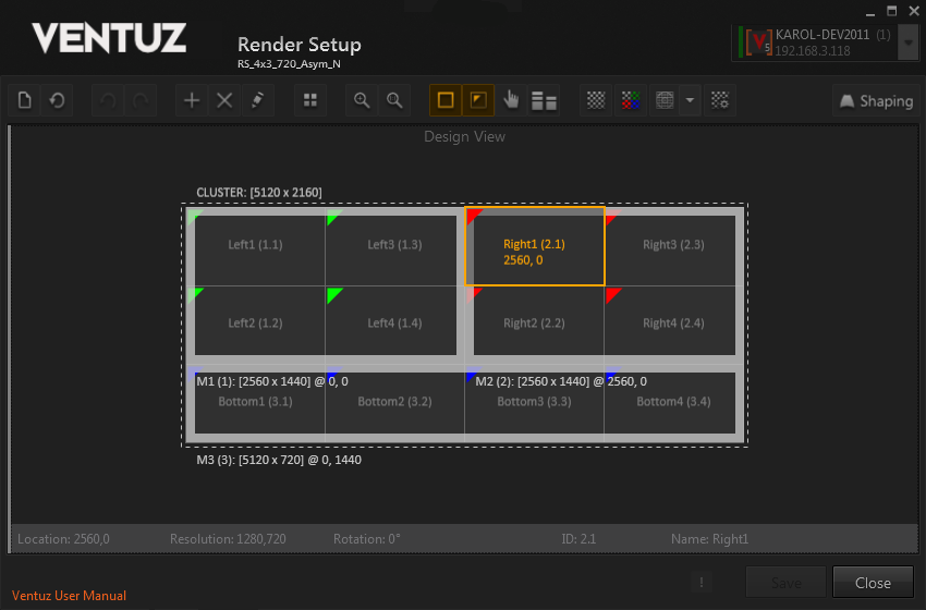
The display wall shown in the example consists of 4x3 displays and has a total resolution of 5120 x 2160 pixels. It is built from 3 machines: two machines have a 2x2 display setup, the third machine has a 4x1 display setup. The dashed frame marks the visual border of the whole Cluster or Render Setup respectively. On top of this frame the visual resolution of the Cluster is displayed. (The Cluster always has the default name CLUSTER.) The broad frame marks the visual border of one machine. Below this border the machine name, its visual resolution and its position is displayed (more details below)! Each display has its name written in the center (with its ID in brackets); if a display is selected its coordinates are shown too. The name and the assigned color can be changed by editing the properties (CTRL + SHIFT + E or Edit properties in the toolbar). If a machine is selected, its ID can be changed to a new free value.
The Toolbar at top of the editor contains several buttons. From left to right their functionality is as follows:

- Create New Setup: Launches the New Setup Dialog to create a new Render Setup based on numeric values
- Reset All: Resets the position of all machines and displays
- Undo: Reverts last modification
- Redo: Re-Applies last reverted modification
- Add Machine: Launches the New Machine Dialog to add a further machine to the existing Render Setup
- Delete Selection: Deletes the currently selected items
- Edit properties: Presents dialog to edit some basic machine and display properties
- Split Selection: Launches the Split Dialog to subdivide selected items
- Zoom to Fit: Zooms and pans to the selected items so that they are displayed centered and fill the available Display Editor space. If nothing is selected zoom and pan is reset so that the complete Cluster is visible.
- Zoom to Cluster / Reset Zoom: Resets zoom and pan to default values
- Show Machine Borders: Toggles the visualization of the machine border
- Show Color Marker: Toggles the visibility of the color marker in the upper left corner of the display fragments
- Show Touch Area: Toggles the visibility of the area that allows to re-map incoming touches to a specific area
- Show Production View: Toggles a side-by-side view of Design and Production view to visualize the relation between actual output and design canvas
- Show test pattern on output: Commands running Ventuz to render a specific test pattern instead of a scene
- Multiply test pattern with output color: The test pattern is colored according to the assigned display color
- Select active test pattern: Show a collection of different test pattern which can by rendered by Ventuz
- Display settings of current test patterns: Modifies active test pattern
- Shaping: The editor switches to the Shaping & Warping editor
To create a new Render Setup launch the New Setup dialogue. This can be done by pressing CTRL + N or clicking on the first button in the Toolbar. This will bring up the following dialogue:
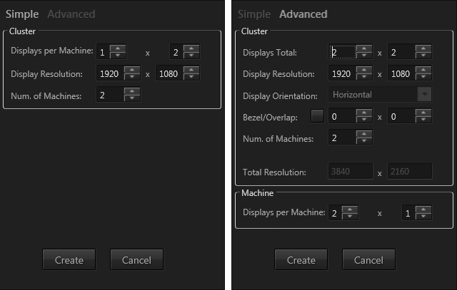
The New Setup dialogue consists of two tabs: Simple and Advanced. In Simple mode one has to specify the number of displays per machine, their arrangement and the resolution per display. Finally, the number of machines has to be specified. Clicking Create will arrange the machines from left to right in the Display Editor. In Advanced mode first of all one specifies the display arrangement for the whole Cluster and the resolution per display. In Advanced mode it is possible to specify a Bezel or Overlap area for displays with frames or projectors. The unit of these values is pixels. In the next step the total display arrangement must be distributed over a certain number of machines. In the Machine section one has to specify the display arrangement per machine if there are multiple possibilities for the whole cluster with N machines. Example: a cluster of 4x2 displays with 2 machines can be created from 2 machines with 4x1 displays aligned vertically or 2 machines with 2x2 displays aligned horizontally.
It is possible to create Bezel values from the physical dimensions of a display. To open this Bezel Helper dialog click on the button left to the bezel values.
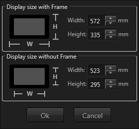
From the display size with frame and without frame (only the visible pixel area) this dialogue calculates the horizontal and vertical bezel values.
The maximum visual resolution for a Ventuz machine is 16384 x 16384 pixel!
Automatic Render Setup from VMS
There is an additional way to get an initial Render Setup if one creates a new entry in the Ventuz Configuration. The Ventuz Machine Service (VMS) is able to retrieve the display configuration from NVIDIA and AMD graphics cards. It reads the Mosaic or Eyefinity configuration and creates a corresponding display arrangement in the Render Setup editor.
For the example above the initial Render Setup from the VMS will look as follows:
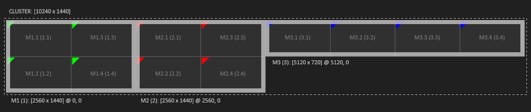
As there is no information about the visual relationship of the machines to each other, they are arranged horizontally from left to right. To achieve the final result you just have to move the 4x1 machine to the bottom of the other two.
Coordinate Space
The machines and displays in the Render Setup Editor lie in a pixel-based coordinate space. The origin of this coordinate space is the top-left corner of the cluster bounding-box. The cluster bounding-box is the smallest bounding-box containing all machines. The X coordinate advances to the right; the Y coordinate to the bottom. Note that even if you move the whole cluster configuration to other coordinates than [0;0], it is reset to [0;0] before it is saved to file. The position of the whole cluster does not affect the render output of Ventuz with the according Render Setup configuration loaded! For a single machine Render Setup this coordinate space matches the coordinate space of a full size Layer in Ventuz. The origin of the world coordinate space in the according Ventuz scene is always in the center of the cluster bounding-box.
Logical vs. Visual Resolution
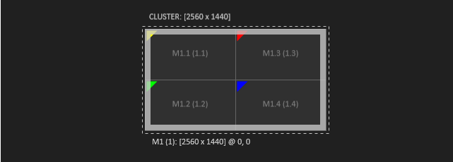
In the context of the Render Setup configuration we talk about Logical and Visual Resolutions. These terms will be explained here. The logical resolution of a machine is defined by the Mosaic or Eyefinity configuration of the graphics board. A 2x2 display setup with a resolution of 1280 x 720 px per display has a logical resolution of 2560 x 1440 pixels.
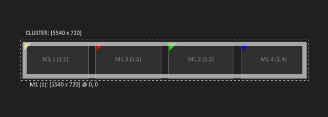
The visual resolution however is defined by final position of the displays in the Render Setup configuration. In the example below the displays are arranged horizontally and have bezel between each other. This leads to the visual resolution of 5420 x 720 pixel.
Manipulating a Render Setup
Selection
Elements can be selected by simply click. Multi selection is possible using modifier CTRL + click or by dragging a selection frame drag around elements.
Elements that can be selected are the Cluster, Machines, Displays and Fragments. The Cluster is the parent of all machines, a machine is the parent of its displays and a display is the parent of its fragments. CTRL + click on a selected element selects the parent directly. CTRL + SHIFT + click selects the parent machine.
| Clicking on the cluster label selects the whole cluster. | 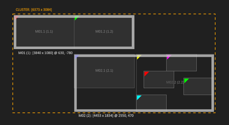 | Machines can be selected at their border. | 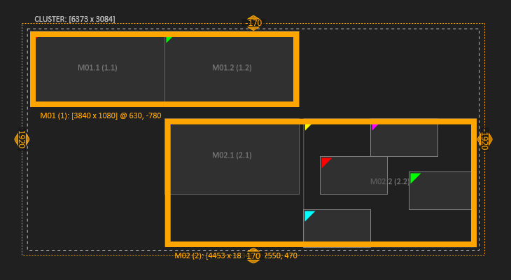
|
| Displays and Fragments behave the same. They can be selected together. Selecting all Displays of a machine is not the same as selecting the machine. | 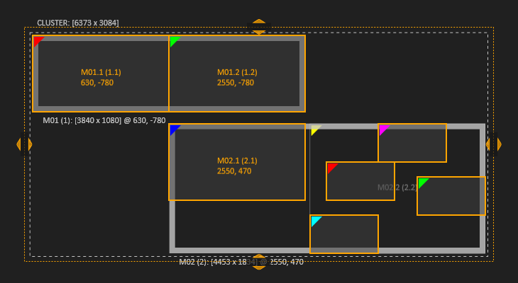 | A multi selection is possible with both, Displays and Fragments. | 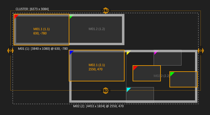
|
| Display 2 of Machine 2 is split into 4 Fragments. | 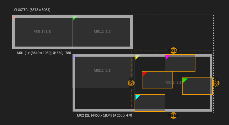 | Even if split into fragments, the display is still the parent and can be selected. For example to reset and combine fragments. | 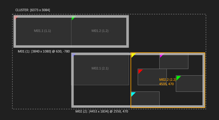
|
Move Elements
After having created an initial setup that matches the actual graphic board output and machines, the elements like machines, displays and split fragments of a display can simply be moved to match the desired design setup. (Compare Screenshots in section Logical vs Visual Resolution above)
Elements are moved freely using the mouse or pixel based using the keyboards arrow keys. Moving elements apart from each other or making them overlap creates a gap or an overlap in the design.
Bezel and Overlap
To create an equal bezel or overlap between multiple elements, it is possible to adjust the amount of bezel or overlap between displays interactively in the Display Editor. If multiple displays are selected, a Shifting Frame is drawn around the selection. It has a handle on each side to change the bezel/overlap horizontally or vertically.
The values in the handles are related to the last selection and are reset on a new selection. The display shifting can also be performed with the Arrow keys and a pressed Shift key! Double-clicking on a handle brings up a dialog to set the bezel/overlap values in pixel or in percent of the display size.
Split and Combine
Machines and Displays can be split into fragments to create complex display arrangements. The Split Dialogue, which is available in the Context Menu or in the Toolbar, provides two splitting procedures. This is useful or even necessary for screens which have an internal daisy-chaining mechanism which allows you to link multiple screens from one output or LED Panels that are fed in a similar manner.
 | 
|
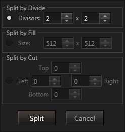
Split by Divide: The selected items are divided equally by the specified horizontal and vertical divisors. This splitting procedure works only if the division results in integer values!
Split by Fill: The selected items are split into parts of a specific size. If the initial item cannot be filled completely by the specified size, the remaining areas are assigned to a part of its own and can be deleted afterwards.
Split by Cut: The selected items are split by performing cuts from left, right, top and bottom according to the specified values. If all four values are larger than zero, the split will result in nine items.
Split machine or display parts can be combined again if they have the original relation of proximity and the selection is a rectangle. The Combine command is available via Context Menu or keyboard shortcut CTRL + SHIFT + C.
The Reset command can be used to bring elements back into their original position (for example to combine split elements). It is available via Context Menu or keyboard shortcut CTRL + SHIFT + R.
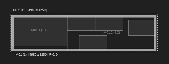
Fragments that are not needed can simply be deleted. For example six 512x512px LED Panels should be fed from one 1920x1080px output. After splitting the 1920x1080 output into fragments of 512x512 px, there will be some leftovers that are not relevant for the design. These can be simply deleted while the 512x512 fragments can be moved to match the desired design canvas.
Combine Machines & Transfer to new Machine
Machines can be combined as well. This can be used either to consolidate the existing setup to fewer machines, or to add another display to a machine. To add a display, a new machine can be added to the setup and combined with an existing machine.
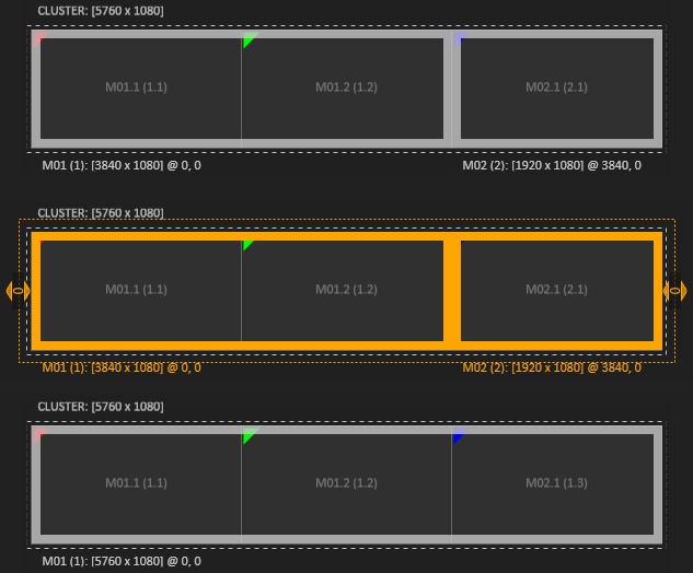
The opposite way is to transfer one or multiple displays from a machine to a new machine. Note that only displays at the edges of a machine can be transferred. It is not possible to transfer the middle display of a 3x1 display machine as this would produce inconsistent results.
Machine ID
The machine ID makes sure that a Ventuz scene can determine which part of an overall cluster content should be rendered. This is done by comparing the current machine ID to the machine ID specified in the Render Setup. Currently the machine IDs are assigned automatically. If a new machine is added to an existing Render Setup configuration, the smallest free ID is taken. If you want to change the System ID of a machine, click on the broad machine border and select 'Edit Properties' from the context menu. In the following dialog you can change the System ID, Name and marker color of this machine.
Design View and Production View
The toolbar button Show Production View opens a side by side view of Design View and Production View. The Production View shows how the graphics are mapped to the actual output signal.
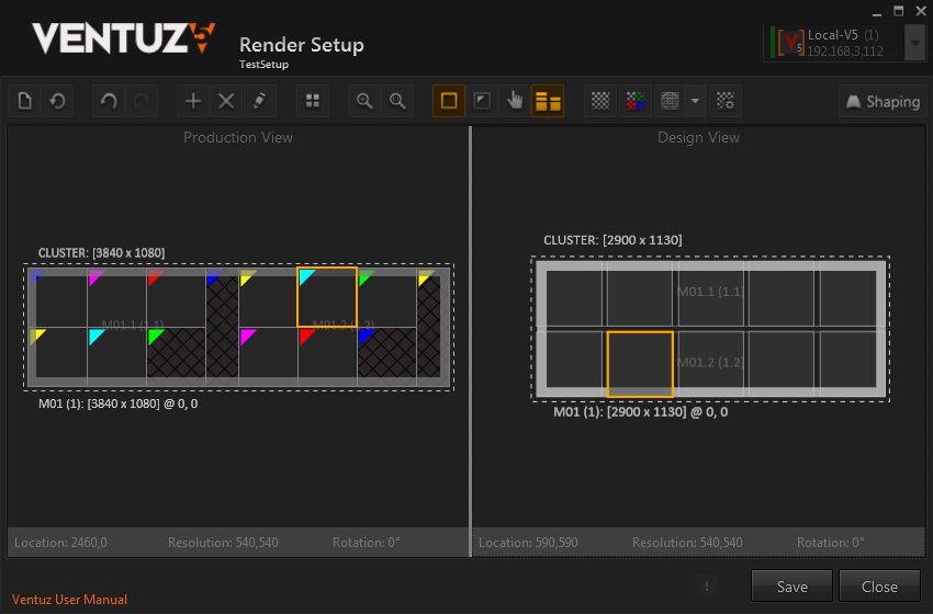
In the screenshot above, two 1920x1080px outputs are used to feed ten 540x540px LED Panels. The fragments that were not needed have been deleted in the Design View and appear cross-hatched in Production View.
A selected element will highlight in both views to see where that part of the graphics will appear in the output signal.
While elements are arranged and split in Design View, few operations are done in Production View:
Recover: Elements that have been deleted can be recovered. click on a cross-hatched element and choose recover from the context menu or CTRL + SHIFT + V recovers the element. It will appear in Design View right of the right most element and can be moved to the desired position.
Arrange Machines: Moving Machines in the Production View is possible to create a better visual representation in the editor and does not affect the rendering.
Touch Area
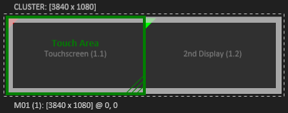
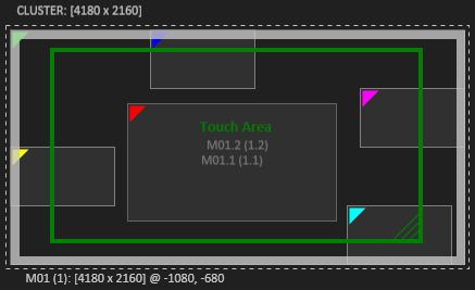
The Touch Area allows remapping of incoming touch data to a custom area of the cluster. Ventuz' Input Subsystem receives the touch data from attached touch devices. The touch is interpreted in normalized coordinates from 0,0 to 1,0 from the top left corner to the bottom right corner. By default, this touch information is applied to the whole cluster canvas the same way, 0,0 top left to 1,0 bottom right. When the Show Touch Area button is enabled in the toolbar, the touch area is represented as a green rectangle. By default, it is locked to the cluster, which results in the default behavior described above. To adjust the touch area, it has to be unlocked via the context menu or the keyboard shortcut CTRL + U. Now the touch area can be adjusted. The size can be changed by click+drag the bottom left green hatched corner of the touch area. It can be moved just like any other element.
Examples and Scenarios
- A setup consisting of one machine with two screens attached. Only one screen is a touchscreen. By default, the touch coming from the touchscreen would be mapped across the whole two-screen wide canvas. The result is, a touch that appears in the middle of the touch screen, does not appear right there, but would be mapped to the middle of the whole display area. Adjusting the touch area so it matches the touchscreen leads to correct and expected behavior.
- In setups that use for example a touch laser device, it is sometimes not possible or undesirable to make the touch laser cover the whole canvas even if only a part of the canvas should be made touchable. In this case the touch area can be adjusted to the same area the touch laser is calibrated to get the expected results.
Keyboard Shortcuts
Here is an overview of the available mouse and keyboard operations.
| View | ||
|---|---|---|
| | Pan | |
| | Zoom | |
| | Reset Pan an Zoom | |
| CTRL + F | Zoom to Fit | |
| CTRL + R | Reset Zoom | |
| Selection | ||
| click | Select | |
| click+drag | Rectangle Selection | |
| click | Context Menu | |
| CTRL click | Single Selection | Select parent item |
| CTRL + SHIFT click | Single Selection | Select parent machine |
| CTRL click | Multi Selection | Add/Remove to/from selection |
| Editing | ||
| move | Move selection | |
| SHIFT move | Move selection without snapping | |
| CTRL + N | Create New Setup | |
| CTRL + Z | Undo | |
| CTRL + Y | Redo | |
| CTRL + + | Add Machine | |
| DELETE | Delete Selection | |
| CTRL + SHIFT + E | Single Selection | Edit properties |
| CTRL + SHIFT + S | Split Selection | |
| CTRL + SHIFT + C | Multi Selection | Combine Selection |
| CTRL + SHIFT + R | Reset selection | |
| CTRL + SHIFT + V | Recover deletes elements | |
| ←, →, ↑, ↓ | Move selection by 10 pixel | |
| CTRL + ←, →, ↑, ↓ | Move selection by 1 pixel | |
| SHIFT + ←, →, ↑, ↓ | Multi Selection | Change distance by 10 pixel |
| CTRL + SHIFT + ←, →, ↑, ↓ | Multi Selection | Change distance by 1 pixel |
| CTRL + L | Lock Touch Area to Cluster | |
| CTRL + U | Unlock Touch Area | |