DMX Nodes
Table of Contents
 | DMX In | Receives DMX data. |
 | DMX Out | Sends DMX data. |
 | DMX Trigger | Receives Art-Net Trigger Events. |
 | DMX from Texture | Sends color data coming from a texture to DMX. |
 | Pan/Tilt | Helps to map pan and tilt parameters to the according DMX out channels. |
Ventuz supports sending and receiving DMX data, using the two protocols Art-Net and sACN, that allow transporting DMX data over ethernet networks.
General settings like network configuration can be found in the DMX Tab of the Machine Configuration.
Project Data channels can receive DMX directly.
DMX In / Out
These nodes are for sending and receiving DMX data. The DMX input node receives data, the DMX output node sends data.
Common properties
- Universe: Sets the universe to send to/receive from. Hint: When the universe is set higher than the used ones - marked as (unused) - In and Out nodes set to the same unused universe can be used locally for testing purposes.
- BaseChannel: Sets the first channel on that universe to send to/receive from.
- Endianness: When using 16-bit values over two channels (see below), set what byte comes first (Lowest or Highest). It depends on the device if Big-Endian or Little-Endian has to be used.
- Enabled: (DMX Out only) Turns the output on or off. In off state and when no other node is outputting on the same channels, the "unused out channels" setting in the machine configuration determines the output data.
- Pause: (DMX In only) Holds the last received value.
- Changed: (DMX In only) Fires whenever a value in an input channel has changed.
Define DMX Channels
To send or receive data, properties have to be added to the node. These are mapped to the DMX channels. The nodes Custom Model is used to add properties to the node.
On the DMX Out node, a click on  adds input properties to the node to send values from Ventuz.
On the DMX In node, a click on
adds input properties to the node to send values from Ventuz.
On the DMX In node, a click on  adds output properties to the node to receive the incoming DMX data.
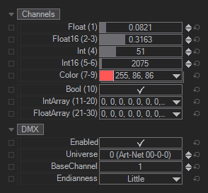
The following types exist:
(remember that a raw DMX channel is one byte and goes from 0 to 255)
- Float (Float): A single DMX channel, mapped from 0.0 to 1.0
- Float16 (Float): A 16-Bit value over two DMX channels (byte order see above), mapped from 0.0 to 1.0
- Int (Integer): A single DMX channel, raw from 0 to 255
- Int16 (Integer): A 16-Bit value over two DMX channels from 0 to 65535
- Color (Color): RGB color over three DMX channels
- Bool (Boolean): Boolean value on a single DMX channel: 0-127 means false, 128-255 means true
- IntArray (Integer[]): An array of consecutive DMX channels of type Int. The length of the array is defined by the user when the property is added to the node.
- FloatArray (Float[]): An array of consecutive DMX channels of type Float. The length of the array is defined by the user when the property is added to the node.
The properties will be mapped to DMX channels from top to bottom, starting at the BaseChannel. It follows the same idea as most DMX devices, that have a set of channels that make sense, and then can be mapped in the universe by setting the BaseChannel. The following table shows an example of how properties of different types are mapped to channels, and how the BaseChannel affects this.
The numbers in parentheses show the actual DMX channels the property uses.
If the BaseChannel is set too high for all channels to fit in the 512 channel universe, an error will be logged.
Color Correction (DMX Out only)
On the DMX Out Node, for all channels of type Color, an optional color correction can be applied. It allows to convert the RGB to a certain Color Space and set a Gain for the R, G and B channels.
Especially when using RGB Led's or Lights, you have to deal with gamma correction, not properly color calibrated lights and the like. So just outputting RGB will probably not look like expected. Setting the color space to match the light's color space and adjusting the gain so a full white actually looks white will produce much more consistent results.
DMX Trigger
Although the node is called DMX Trigger, this is specific to Art-Net. Art-Net has a feature to send trigger commands, macro keys and even keystrokes over the net. The DMX Trigger node receives these commands, and if they match the type and index set in the properties (e.g. "Macro 3"), the output event is fired.
DMX from Texture
The node is made to send color data taken from a texture and output it to DMX - for example to LED strips or panels. The node can read from any Ventuz texture. It can then be sampled down to a small size and be output as RGB to DMX.
Properties
- Enabled Turns the output on or off. In off state and when no other node is outputting on the same channels, the "unused out channels" setting in the machine configuration determines the output data.
- Layout Sets the RGB layout for the channels, i.e. the channel order and if one pixel maps to 3 or 4 DMX channels.
- SpanMode: When sending plenty of color data to a bigger LED panel, the amount of channels needed can easily span multiple DMX universes. The SpanMode sets the behavior when a universe is about to run out of channels:
- Pixels: In this mode, if there are not enough channels in the universe left to fit all channels of the current pixel inside, the last couple of channels in the universe will stay unused and all channels of the pixel will be placed in the next universe.
- Channel: All channels of the universe are used. If not all channels of the current pixel fit in the universe, the pixel will be split and the first channels are used to fill up the universe while the remaining channels of the current pixel are placed in the next universe.
- None: The node does not span across multiple universes. Instead, the node just uses the channels available in the set universe. Any color data that would exceed this universe is ignored.
- Delay: This sets a delay between the incoming image and the DMX output in frames. This is always at least 1. If there is a lot of video delay and the synced lights are too fast, the delay can be increased.
- Texture: The input texture the color data is read from.
- SizeX and SizeY allow to set the texture to the size of the - i.e. - LED installation. The texture will be down sampled to this size before outputting any values.
- Color Correction: See the corresponding group in the DMX output node.
Strips
To actually output something, 1D strips or 2D panels have to be defined. The down sampled input texture has to be mapped to these. Per strip/panel, the position in the down sampled texture, the size, into which direction it goes and on which DMX universe and channels to output have to be defined.
- Universe: Sets the universe to send on. If the strip/panel is so big that it does not fit into the universe, the consecutive universes after it will be used.
- Channel: The base channel for a strip or panel. From that channel on the pixels will be set with the layout specified above.
- X and Y: The starting position of the strip/panel in the down sampled texture. 0,0 is upper left corner.
- Direction(1) and Length(1): Sets how many LEDs a strip has and into which direction it goes in the texture. E.g. if there are a lot of strips with 20 LEDs each hanging from the ceiling, choose some X in the texture and set Y to 0, Direction to "down" and Length to 20.
- Direction2 and Length2 (2D panel only): Sets direction and length of the second axis. For example on a 8x8 LED panel with 64 LED's, where the first LED is in the upper left corner, and the 9th pixel is the very left LED in the second row. Both, Length1 and Length2 are set to 8, while Direction1 is set to "right" and Direction2 is set to "down".
- Zigzag (2D panel only:): Some 2D panels a built in a particular way: In reality they are just long strips and they are layout-ed in a zigzag way. Looking at the 8x8 panel from above, the first 8 LEDs would go from left to right but then the next 8 in the second row go from right to left. Then the 8 in the third row from left to right again, and so on. To send data to a panel like this where every second row is the wrong way around, this option can be checked.
Pan / Tilt
Light fixtures often come in the form of moving heads, where the light can pan and tilt back and forth. The pan/tilt is normally described as one or two DMX channels and goes from "the one side" to "the other side", where the values go from minimum to maximum.
The Pan/Tilt node is a helper node to translate useful parameters for the corresponding DMX node. The node itself does not output any DMX data, it just helps to do some math. The node outputs values between 0 and 1, which are then bound to the channels used for Pan and Tilt on the DMX Out node. These channels on the DMX Out node are expected to be Float or Float16.
Setup
The node needs to know the lights pan or tilt range. This can be found in tech specs of the light.
- PanCenter: Sets at which DMX value the pan is in its middle. Normally lights use the full 0 to 1 range, so often the default 0.5 is the center.
- PanInvert: Just flips the whole values in case left/right is the wrong way around.
- PanIsEndless: Some light can spin their pan endlessly and do not need to go back. E.g. if the pan range is 360° and the pan goes up to 1.0 and then jump back to 0.0, the light does not rotate backwards but simply continues rotation. If the connected device supports this, this option enables it.
- PanRange: Sets how much the light can pan around. This can e.g. be 360°, or some lights can do two revolutions of the pan motor and do 720°.
- TiltCenter: Similar to PanCenter, but for tilt. It sets the value at which the tilt is neutral, e.g. the light goes up.
- TiltInvert: Similar to PanInvert, this flips the tilt if it goes the wrong way around.
- TiltRange: Sets the range of the tilt. For most lights, this is between 180° and 270° for most lights. Otherwise they shine at their own base.
Method
After setup, the properties under Method are the actual input values, i.e. the Pan and Tilt values in degrees that the light should follow.
- Direct: This is the simplest method. It just expects Pan and Tilt in degrees and properly calculates DMX channel values from that.
- Matrix: A world matrix can be inserted. The node takes the forward vector of that matrix (the +Z vector) and calculates Pan and Tilt from that. This way a moving light can be synced to an object in the Ventuz scene. For example a mesh, or a Vive controller points at something and all the lights in the room follow. Other devices like 3D tracking hardware also often output a world matrix.
- X/Y: This method basically takes a TargetX and a TargetY value and interpolates between the four pan/tilt presets. So it allows to set up an area that can be traversed with the Target values. It can create a perspective corrected 2D control e.g. for a wall or screen.
- TargetX: The input value for the X direction.
- TargetY: The input value for the Y direction.
- Pan00: This will be the pan output when TargetX is 0 and TargetY is 0.
- Pan10: This will be the pan output when TargetX is 1 and TargetY is 0.
- Pan01: This will be the pan output when TargetX is 0 and TargetY is 1.
- Pan11: This will be the pan output when TargetX is 1 and TargetY is 1.
- Tilt(X)(Y): The Tilt values are handled the same way as the Pan values.