Navigation

Ventuz 6 Quick Guide

  • Introduction
  • Getting Started
  • Ventuz Editions
  • Designer Overview
  • Ventuz System Requirements
  • Configuration
  • Video/Audio Configuration
  • Machine Configuration
  • GPI Configuration for Runtime or Director
  • Optimize Rendering Performance
  • Supported Formats
  • Supported Hardware
  • Multisampling / Anti-Aliasing
  • Input Subsystem
  • Ventuz Proprietary Files
  • What's new
  • FAQ
  • Common Mistakes
  • Deployment
  • Migration Guide
  • Ventuz 5 Migration Guide
  • Summary Shortcuts

Ventuz 6 Designer

  • Index
  • Getting Started
  • Designer Options
  • Designer Overview
Projects & Scenes
  • Projects and Scenes
  • Project Browser
  • Project Properties
  • Project Maintenance
  • Project and Scene Data
  • Scene Tree
  • Scene Management
  • Scene Statistics
  • Deployment
Interface
  • Designer Interface
  • Renderer Window
  • Realtime Rendering
  • Optimize Scene Performance
  • Performance Statistics
  • Transformation Gizmo
  • Render to Disk
  • Camera Navigation
  • Isolated Objects
  • Manipulate Objects with Gizmos
  • Layer Editor
  • Common Layer Properties
  • IPP Effects
  • Color Correction FX
  • Distortion FX
  • Filter FX
  • Layer Editor Shortcuts
  • Hierarchy Editor
  • Working with Nodes
  • Containers
  • Find and Replace
  • Shortcuts Hierarchy Editor
  • Content Editor
  • Working with Nodes
  • Containers
  • Content Editor Shortcuts
  • Toolbox
  • Property Editor
  • Project Data and Scene Data
  • Property Groups
  • Shader Editor
  • Text Editor
  • Scene Tree
  • Message View
  • Stage Editor
  • Container Outline
  • Watches Editor
  • Animation Editor
  • Animation and State Engine
  • Templates
  • Template Engine
  • Shortcuts Animation Editor
  • Text Rendering
  • Text Editor
  • Character Sets
  • Geometry Import
  • Input Subsystem
  • Multitouch
  • TUIO Protocol
  • Open Sound Control
  • How to work with Head Mounted Displays
  • Cluster
  • Multi Display Setups and Shaping
  • Warping, Soft Edging and Masking
  • Available Nodes
  • Animation Nodes
  • Material&Color Nodes
  • Data Nodes
  • Geometry Nodes
  • Interaction Nodes
  • IO Nodes
  • Layers
  • Light Nodes
  • Logic Nodes
  • Render Option Nodes
  • Slides Nodes
  • Sound Nodes
  • Text Nodes
  • Texture Nodes
  • VR Nodes
  • World Nodes

Ventuz 6 Node Reference

ANIMATION
  • Mover
  • Alternator
  • Simple Control
  • Timeline Control
  • Anmation Rig
  • Keyframe Animation
  • Animation Group
COLOR/MATERIAL
  • Alpha
  • Fog
  • Ground Fog
  • Sky Box
  • Color to RGBA
  • HSLA to Color
  • RGBA to Color
  • Color Transformer
  • HLSL Shader
  • Color
  • Material
  • Color Picker
  • Substance Material
DATA
  • Database
  • Excel
  • JSON
  • RSS Feed
  • Resource Linker
  • Text File
  • XML
GEOMETRY
  • Rectangle
  • Rounded Rectangle
  • Gradient Rectangle
  • Overlay Rectangle
  • Cube
  • Circle
  • Sphere
  • Cylinder
  • Cone
  • Torus
  • Chart
  • Random Points
  • Mesh Loader
  • Geometry Import (Live)
  • Volume
  • Get Bounding Box
  • Arrow
  • Particle System
  • Path Renderer
  • Geometry Renderer
INTERACTION
  • Interaction Rect
  • Touch Button
  • Touch Excluder
  • Touch Marker
  • Touch Paint
  • Touch Pattern
  • Touch Proxy
  • Touch Ripples
  • Touch Transformations
  • Web Browser
  • Touch Teleport
  • Touch Simulator
INPUT/OUTPUT (I/O)
  • GPI
  • Joystick
  • Keyboard
  • MIDI
  • Mouse
  • Network
  • Open Sound Control
  • Serial
  • Timecode
  • DMX
LAYER
  • 3D Layers
  • 3D Layer Reference
  • 2D Layers
  • PSD Import Layer
  • Others
LIGHT
  • Light Sources
LOGIC
  • Array Processing
  • Convert To Text
  • Cluster Synchronization
  • Counter
  • Date Time
  • Directory
  • Dispatcher
  • Enumeration
  • Expressions
  • Invert
  • Log
  • Loop Breaker
  • Math Effects
  • Matrix Operations
  • Scene Event
  • Script
  • String Operations
  • System ID
  • Text Splitter
  • Timer
  • Toggle
  • URL
  • Value Switch
  • Value Buffer
  • Variables
  • Visual Indexer
RENDER OPTIONS
  • Alpha Blending
  • Color Write
  • Alpha Testing
  • Clip Plane
  • Filter
  • Mask
  • Mirror
  • Effect
  • Render Cube Map
  • Draw Modes
  • Stencil
  • ZTesting
SOUND
  • Audio Clip
  • Sound
  • Volume Control
  • Audio Analysis
SLIDES
  • Slide Manager
  • Slide
  • Slide Port
  • Pivot
TEXT
  • Text Effects
  • Text Layouts
  • Text Rendering
TEXTURE
  • Background
  • Hatch
  • Image
  • Texture
  • SVG Loader
  • Gradient Texture
  • Live Video
  • Movie Stream
  • Movie Frame
  • Movie Clip
  • Texture Loader
  • Snapshot
  • Snapshot Framebuffer
  • Texture Saver
  • Video Source Selector
  • VIO Input
  • Spout Receiver
  • NDI Receiver
  • Substance Loader
VR/AR
  • Tracked Devices
  • Draw Tracked Devices
WORLD
  • Axis
  • Billboard
  • GetWorld
  • SetWorld
  • Arrange
  • Ticker
  • Layout
  • Group
  • World Z Sort
  • YesNo
  • Switch
  • Spread
  • Filter Pass
  • Set Pass
  • Hierarchy Container
  • Scene Port
  • Content Container
  • Template Port
  • Container Info
  • Camera
  • Paths

Ventuz 6 Configuration Editor

  • Configuration
  • Machine Configuration
  • Video/Audio Configuration
  • Web Configuration Editor and License Manager
  • Render Setup Editor
  • Warping and Soft-Edging Editor
  • Supported Hardware
  • How to Setup a Cluster Render

Ventuz 6 Director

  • Application Settings
  • Assets
  • Channels
  • Command Line Options
  • Content References
  • Designing Templates
  • Environment
  • Glossary
  • Index
  • Introduction
  • Pages
  • Playlist
  • Plug-Ins
  • Project Data
  • Property Editor
  • Shortcuts
  • GPI Configuration
  • Shot Box
  • Show
  • Taking Action
  • Timeline
  • Topology
  • User Interface
  • Director Mode
  • Macros

How To

  • How to Run Ventuz
  • How to Work with Designer
  • Ventuz Designer Drag&Drop workflow
  • How to use Head Mounted Displays
  • How to work with Shadows
  • How to use Emoijs
  • How to Build a Template
  • How to use Newtek NDI
  • How to Create Visuals Loader Node
  • How to Remote Control with a Phone
  • How to Setup a Cluster Render
  • How to use a Mixed Frame Rate Cluster
  • How to use Tracking
  • How to work with 3D Reference Layers
  • How to create a Firework Particle System
  • How to use DDS with new Block Compression modes
  • How to setup Spout with Ventuz
  • How to use the Substance Integration

Keyboard Shortcuts

  • Summary Shortcuts
  • Layer Editor Shortcuts
  • Hierarchy Editor Shortcuts
  • Content Editor Shortcuts
  • Animation Editor Shortcuts
  • Director Shortcuts

Advanced and Development

  • Command Line Options
  • Remoting Overview
  • Remoting 4
  • Remoting 4 via Websockets
  • Deprecated Remoting
  • Ventuz IP Ports
  • Ventuz Machine Service
  • Remoting Machine Signature
  • TUIO
  • .NET Scripting
  • HLSL Shader Programming
  • Ventuz API and SDK
  • Ventuz VIO API
  • Ventuz File Format (VFF)
  • Ventuz Stream Out API

General Reference

  • Terminology
  • Manual Index

Miscellaneous

  • Presets
« Previous Article
» Index «
Next Article »

Camera

Table of Contents

  1. Projection
  2. View
  3. Access a Tracked Camera
  4. Offset a Camera Origin
  5. Design Eyepoint

Camera This node adds a Camera including View and Projection to a 3D Layer

A Camera Node can be added to the hierarchy to create a virtual camera. It has two Property Groups to set up Projection and View separately. Together they define the characteristics of the camera.

While multiple cameras can be defined, only one camera is active per 3D Layer. The active camera is marked by a red dot. The camera is set in the Layer Root. There, also toggling or even interpolating between multiple cameras can be done. A specific camera node can be set active with the Activate Camera entry in the the context menu of the node or via the Activate Camera Button at the very bottom of the Property Editor when the node is selected.


You can use the Free Flight Mode inside the Render Window, fly to your desired position, click the From Freeflight Button in the bttom of the Property Editor to use your actual position and fov for the selected camera.

View and Projection

Projection

Projection simulates the effect of perspective shortening (i.e. objects farther away appear smaller). This is often defined by specifying a view angle (also called field of view). When a more schematic look is required, this can also be an orthogonal instead of a perspective projection which does not have any perspective shortening at all.

Both, Field of View and Orthogonal have Center input properties X and Y that can be used to shift the center of the projection. The projection also specifies the Near and Far planes, who define the Z value of the closest and farthest point that is still rendered as part of the view frustum.

Field of View defines the camera viewing field by the angle between two opposite sides of the viewing frustum. The Fov input property specifies that angle, FovAxis specifies if those are the left and right (horizontal) or the top and bottom (vertical) sides. The angle between the other two sides is automatically calculated based on the Aspect and AspectRelation properties:

  • Relative: The Aspect property is multiplied with the aspect of the render area in the Renderer Window. With the Aspect Property set to 1 a circle will always appear round, independent of the aspect ratio of the render area. The total aspect ratio will be provided in the AspectResult output property.
  • RelativeLayer: Much like Relative, but the Aspect property is multiplied with the aspect of the current layer.
  • Fixed: The Aspect property will directly be used and the ratio of the render area ignored. The AspectResult output property will be equal to the Aspect input property.

If there is no camera node in the scene, Ventuz will use a default projection which is the equivalent of a 45 degrees Field of View projection with the aspect ratio implied by the output resolution set in the Project Properties.

Orthogonal is a special projection that has no perspective shortening at all. It is often used for schematic views or other situations where perspective shortening would be confusing. The Input Properties Width and Height define the width and height of a 3D space volume that will be displayed in the render output. The orthogonal projection basically cuts out this volume straight out of the World/View space and flattens it along the Z-axis.

Matrix can be used to set up or connect a custom projection matrix. A custom matrix could for example be calculated manually or delivered by a third party device.

View

The view matrix is responsible for simulating the position and orientation of a virtual camera. The Camera Node has different capabilities to set up the view matrix:

Pan, Tilt, Roll has position and orientation properties. So the camera can be placed in the 3D World with the X,Y and Z Position and then panned, tilted and rolled just like a real camera.

Look At is always oriented towards the Target coordinates. The camera can be moved by the X,Y and Z Position while it always looks at the specified target. Thus, the rotation is calculated automatically while the Roll can be set manually.

Orbit makes it easy to rotate the camera around a target using Yaw, Pitch and Roll. The Target's X,Y and Z Position can be set as well as the Distance from the camera to the target.

Matrix offers to use a custom view matrix. The presets zero and identity matrix can be used or modified manually or the Matrix Property can be connected to a matrix coming from for example a Matrix Node or a Script.

Access a Tracked Camera

Whenever we are working with Head Mounted Displays or Camera Tracking Systems the default camera is automatically controlled from the outside. However sometimes we need to adjust the Near and Far Plane of the camera to get rid of clipping. To do so simply create a Camera Node and switch the View and Projection Property Group to Tracked.

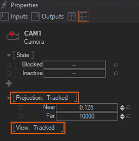
Make sure to switch the View and Projection to Tracked otherwise you will get weird results!

Offset a Camera Origin

Especially when working with Head Mounted Displays you will come to the point where you need to change the Camera origin to morph from one location in the scene to another. To so you can simply add Offsets to camera by clicking the Add Offset button.

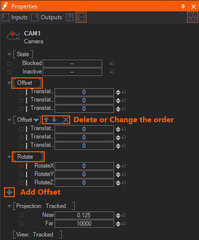
An Offset allows you to translate the Camera by the TranslateX,Y,Z properties. The Rotate provides Rotate X,Y,Z to rotate the Camera.

The order of how the offsets are multiplied togther is defined by the order and can easily be changed by reordering the Property Groups.

Beside Translation and Rotation you can also use a Matrix to apply an Offset to your camera.

Design Eyepoint

At times you might need to calculate lighting independently from the camera's actual position. Especially projection mapping setups need to be able to have different locations for the rendering point and for the viewer's point. This is because you need to render a scene from the position of the projector in order to map it correctly onto the projection's screen. But still the scene's specular points and reflections need to be calculated from the point of view, for example an audience in front of the screen. This becomes even more visible when using more than one projector, each creating different specular reflections.

The Design Eyepoint can be attached to an anchor in the scene that is located at the position of the viewer. Now regardless of the position of the active camera, all shaders will use that position as the camera position for lighting purposes.

See also:
  • Camera Navigation
  • Renderer Window
  • Head Mounted Displays
  • Camera Tracking

« Previous Article
» Index «
Next Article »
Copyright 2020 Ventuz Technology