Project Data and Scene Data
Table of Contents
Project Data
The Project Data of a project contains properties that do not belong to any individual node but the project itself. Imagine a sports event like for example a soccer match. While there will be multiple Ventuz scenes to show different graphics or to separate different parts of the match (e.g. pre-show, main match, post-discussion), the score, team names and so on are common to all scenes. At the same time, those properties have to be adjusted and editing copies of the values in each scene individually is error prone at best.
Instead, the Project Data allows the user to create a set of data channels on the project itself. Each data channel provides a value that can be bound to multiple Ventuz nodes. They can be bound to any node in any scene regardless of its location, whether it is on the root level or hidden deep within a hierarchy of containers. Using Project Data can therefore greatly simplify the way a scene is build, especially when the hierarchy of containers gets complex.
When a scene is loaded, any bindings between project data channels and node properties are automatically resolved and as long as the property still exists, the project data work as if they would have been a part of the scene itself. If a scene is opened and a project data channel has been removed since the last time the scene has been changed, the binding is simply not resolved. So in general, project data just work as expected and a user does not have to concern himself with the mechanisms involved.
It usually makes sense to plan what project data channels make sense for a project and allocate them at the beginning of a projects design phase. Each channel should convey the meaning of being an important, characteristic property of the project as for example all project data will be part of the project data panel inside Director. Try to avoid allocating data channels simply because it is an easy way to connect distant parts of a scene with each other!
Adding New Properties
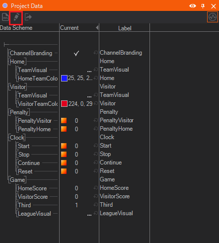
To edit Project Data -click on the edit button highlited in the screenshot. A dialog occures to point the fact that Project Data cannot be edited inside the Project. After confirmation the Project is closed automatically and the Project Data edit mode appears.
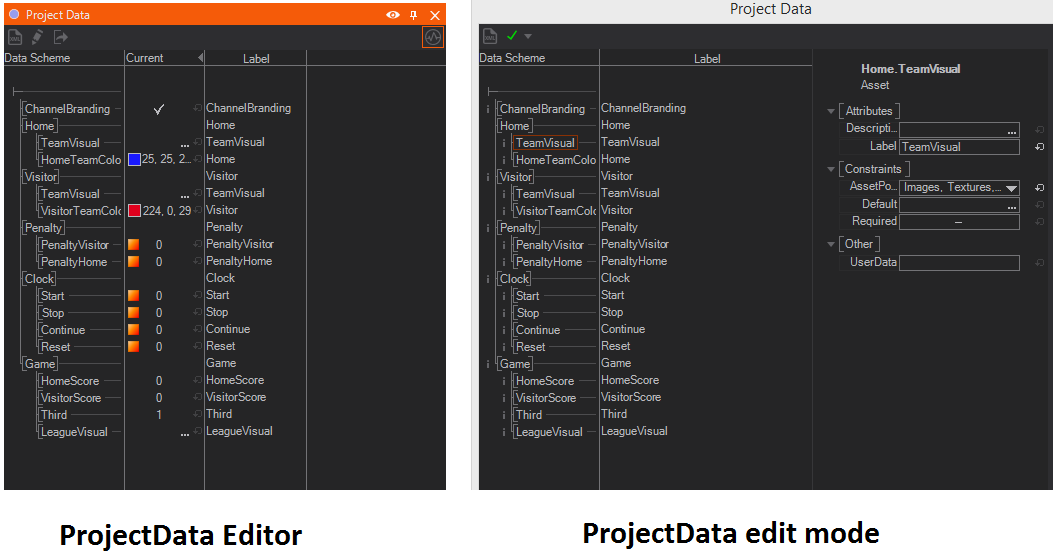
The left side of the Project Data Editor shows a tree of data channels very much like the Animation Editor. For example, all nodes that represent a clock might be bound to a master "start" event in the project data. As shown in the screenshot above, data channels can be grouped by folders. By -clicking on any channel, detailed information is presented in the Property Editor section on the right.
The toolbar at the top of the dialog contains the Project Data Model button as well as the Project Data Validation button. By pressing the former, an XML version of the data model is generated that is mainly useful when using the Remoting Capabilities of Ventuz to set values via a customized, external control application. By pressing the validate button, a list of errors or warnings is produced. Ventuz performs a number of sanity checks to ensure that no problems (e.g. name clashes) arise when project data values are addressed via Remoting.
The validation button updates its icon automatically whenever the data model changes. Make sure that no errors or warnings exist before saving changes!
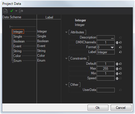
To add or remove data channels, -hold on a channel or folder. If no channel exists yet or a channel should be added on the root level, -hold on the root itself, T-junction in the top left corner (highlited in the screenshot). Once the project data is complete, press OK and open the project.
Using the Project Data Editor
When working on a scene, project data is represented in the Project Data Editor docking window. To open it, either use the menu entry in the View main menu or press Shift + F12. Although the editor looks very much like the edit dialog in the previous section, it serves a different function. Neither can new channels be added/removed nor can the structure be changed. However, node properties can be bound to the project data channels the same as binding properties between two nodes: dragging a property from the Property Editor and dropping it on a data channel.
No arrow is drawn in the Hierarchy or Content Editor to represent a binding. To remove a binding, right-click and hold on the data channel and click the X next to the node name. This context menu is also a great way to find out to which nodes the value is bound
By changing the value in the current column or triggering a method by pressing the orange button, the effect is propagated to all the bound notes through out the scene. The great thing about project data is that it can always be found in a central place, the Project Data Editor, which therefore can act as a master control panel for your scene if used properly.
It's possible to copy&paste (parts of) the Project/Scene Data tree. If you copy it to a text editor, you will get the XML representation of the data model!
DMX Support
Project Data channels can be controlled by DMX, respectively Art-Net or sACN. Besides the DMX Nodes, this is an additional, easy way to receive incoming DMX data.
When Project Data channels are created or edited, there is an attribute called DMXChannels. This attribute determines how many DMX Channels this item should cover. Setting this value to 0 means this item will not receive any DMX data.
The following types are supported:
- Single: 1 to 3 channels. Min and Max must be set, the value will map the DMX range from Min to Max.
- Integer: 1 to 4 channels. Min and Max must be set, the value will map the DMX range from Min to Max.
- Boolean: 1 channel. 0-127 means false, 128-255 means true.
- Event: 1 channel. Event fires when DMX value goes from under 128 to over 128.
- Color: 3 or 4 channels. 3 Channels will be read as RGB, 4 channels as RGBA
- Enum: 1 channel. DMX 0-255 range will be evenly mapped to all enumeration values.
- BooleanArray: 1 to 512 channels. MinLength must be at least the number of DMX channels. Values will be false for 0-127 and true for 128-255
- ByteArray: 1 to 512 channels. MinLength must be at least the number of DMX channels. Values will be the exact content of the DMX channels. This can be used to get "raw" DMX.
Equal to DMX Nodes, the project data items are mapped to DMX Channels in order.
The project data has an export button  to export an html sheet that shows a DMX project data channel list. This is helpful to set up the DMX sending device.
To actually receive DMX on the project data, it has to be turned on in the General DMX Settings in the DMX Tab of the Machine Configuration. Universe and Base Channel are also set there.
Scene Data
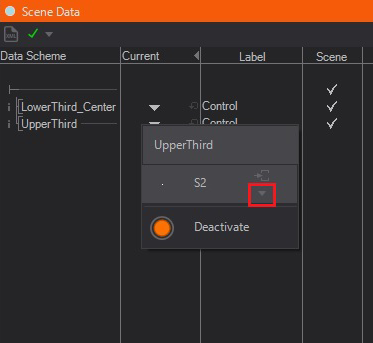
The Scene Data Editor looks and works similar to the Project Data Editor. However, as the name implies, each scene has its own set of scene data channels but shares the same set of project data channels. Therefore new channels can be added/removed only while the scene is open. Again, data channels can be directly bound to any node property regardless of where it is in the scene.
The Scene Data has a special role when it comes to controlling a scene from an external application and replaces the now deprecated Externalizing Mechanism used in previous Ventuz versions.
The Scene Data Editor has an additional column labeled Scene. The exact meaning of this column is discussed as part of the Template Engine. As a rule of thumb, if a data channel is supposed to be used as part of the Template Engine (and be visible to the end-user in Director), the flag should be set. If on the other hand the data channel should not be accessible via the Template Engine, the flag should not be set. For example, Ventuz 3 externalized properties are converted to scene data channels without this flag when the scene is opened in Ventuz 4 or later for the first time.
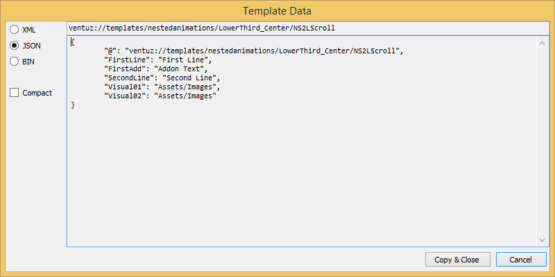
Template Data
The Scene Data Editor provides the Template Data of each Template. This is helpful wherever it is needed to manually set the Template Data, for example when working with the Template Port or when it comes to Remoting. The Dataset can be used as a pattern for dynamically generated Template Data.
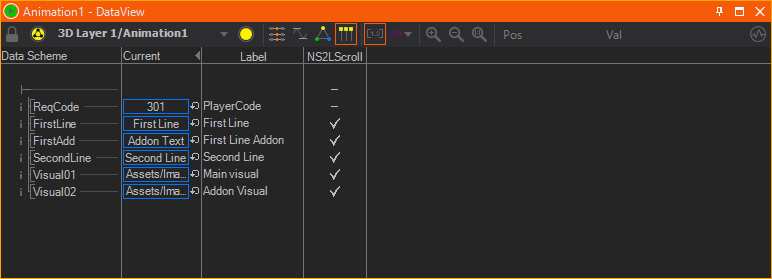
Animation Data
The third level of data is the Animation Data. The data channels in that data belong to a single Keyframe Animation Node. The primary use of Animation Data is to define template parameters. Each present state of the animation is listed as a column and by setting the flag in a column/row combination, a data channel is associated as required data for that state. For more information, see Templates.
DataItems
A DataModel defines a list of DataItems. The following types of DataItems exist:
| Name | C# Type | Modes | Description | Attributes |
|---|---|---|---|---|
| Animation | - | - | The Animation item defines a field that addresses a possible sub-template. The actual value of this field is null or a data instance (TemplateData) of a sub-template. | Required |
| Trigger | - | RW | A Trigger can be either an asynchronous event sent out to the remote client (R), a trigger sent from the remote client to Ventuz (W) or both (RW). | |
| Group | - | (RW) | A Group contains multiple sub-DataItems and acts like a folder. The mode is the sum of all sub-items only defines if the items below are readable and/or writable. The group itself has no value. | |
| Float | float | RW | A floating point value | Default, Min, Max, Speed |
| Double | double | RW | A double precision floating point value | Default, Min, Max, Speed |
| Integer | int | RW | An integer value | Default, Min, Max, Speed |
| Boolean | bool | RW | A boolean value | Default |
| String | string | RW | A string value | Default, MaxLines, MinLines |
| Enum | string | RW | A string value of type that matches the values of an enumeration. The possible values are define in the field Elements. | Default, Elements |
| Color | Color | RW | A color value | Default, Alpha |
| Asset | Uri | RW | A general Uri value that addresses one or multiple asset pools | AssetPools |
| FloatArray | float[] | RW | An array of float values | Default, MinLength, MaxLength |
| DoubleArray | double[] | RW | An array of double values | Default, MinLength, MaxLength |
| IntegerArray | float[] | RW | An array of integer values | Default, MinLength, MaxLength |
| BooleanArray | bool[] | RW | An array of boolean values | Default, MinLength, MaxLength |
| ByteArray | byte[] | RW | An array of byte values | Default, MinLength, MaxLength |
| StringArray | string[] | RW | An array of string values | Default, MinLength, MaxLength |
Data Items Meta Data
All Data Items are described by meta data that can be edited in the Property Editor after clicking it. For example the Ventuz Director uses them to display Template and Project Data properly for the operator of the program. In Remoting you can use the Data Model's Meta Data to accomplish similar results. Below you can see how Ventuz handles these meta data.
General Properties
Besides the Ventuz specific meta data you can define your own data using the UserData property. This is not used by Ventuz anywhere and you can safely use it for information specific to your own application.
Each type of the Data Channels has a Label property that defines the user friendly display name of the channel. As opposed to the data channel names, labels can consist of special characters, e.g. spaces. In addition they are not used to identify a channel, so the data model can have duplicate labels. Similar to the label, the Description is used to present further information to the user - e.g. in the Ventuz Director this is displayed while hovering over the data item.
Format is somewhat specific to the Ventuz Director and its template based workflow - when creating a Page from a template you can decide to automatically create the page's display name and/or description from the current values of the template data. The format property defines what to use from each data item for the automatic naming. The table below shows the possible options - the dropdown of the property also displays some presets that you can choose from.
| Data Types | Value | Effect |
|---|---|---|
| all | empty string | Not used in the automatic naming. |
| !X | Shows the value of this data item in the display name of the page instead of in its description. | |
| float, double | fX | Fixed point number with X decimals. X defaults to 2. |
| cX | Currency with X decimals. X defaults to 2. | |
| eX | Exponential notation with X decimals. X defaults to 6. | |
| nX | Number with X decimals. X} defaults to 6. | |
| p | Percentage. Note that the displayed number is therefore multiplied by 100. | |
| integer | dX | Integer number with minimum X digits. X defaults to 1. |
| xX | Hexadecimal number with minimum X digits. X defaults to 1. | |
| boolean | X;Y | X if true, else Y. |
| string, enumeration | X | Show string truncated to X characters. Do not truncate if 0. |
| -X | Show string truncated to X characters and show elipsis for truncated characters. | |
| color | c | Known color name or expressed as Red, Green, Blue values. |
| # | Hexadecimal string. | |
| array | 0 "X" | Show number of values followed by X |
| csv | Show values as comma separated list. | |
| asset | nx | File name with extension. |
| n | File name without extension. | |
| uri | Full file path. |
In the above descriptions, X and Y are wildcards.
Constraints
Each different type of data channels has a set of Constraints guiding the user when setting values on these items. Below is a list of all constraint properties and their functions in Ventuz.
| Data Types | Property | Usage |
|---|---|---|
| all | Default | The initial value of the data item. |
| float, double, integer | Max | Maximum possible value. Value will be set to Max if it is greater. |
| Min | Minimum possible value. Value will be set to Min if it is less. | |
| Speed | Change speed when using drag and slide to change the value. | |
| string | Choices | You can add a comma seperated list of values to change the text box to a combo box, so that the user can choose from predefined values as well as type a custom text. |
| MaxLines | Maximum number of lines. Will be truncated to this number of lines if it is exceeded. | |
| MinLines | Minimum number of lines. Will be truncated to this number of lines if it is underrun. | |
| RegEx | A regular expression that the given text is tested against so that only input of a certain form is allowed. If it does not match the text cannot be set. | |
| color | Alpha | Whether alpha can be defined as well or not. |
| enumeration | Elements | Comma separated list of elements that the user can choose from. Note that Default must be present in this list. |
| array | MaxLength | Maximum allowed number of values in the array. |
| MinLength | Minimum allowed number of values in the array. | |
| asset | AssetPools | The allowed asset pool to choose from. All assets that are not associated with any of the chosen pools will be ignored. Misc allows any type of file. This also filters the list of assets in the shotbox of the Ventuz Director when it was opened by clicking on the asset channel. |
| Required | If set it disallows to leave this data item empty. |