Table of Contents
Ipp Effects: Distortion
Drop Shadow
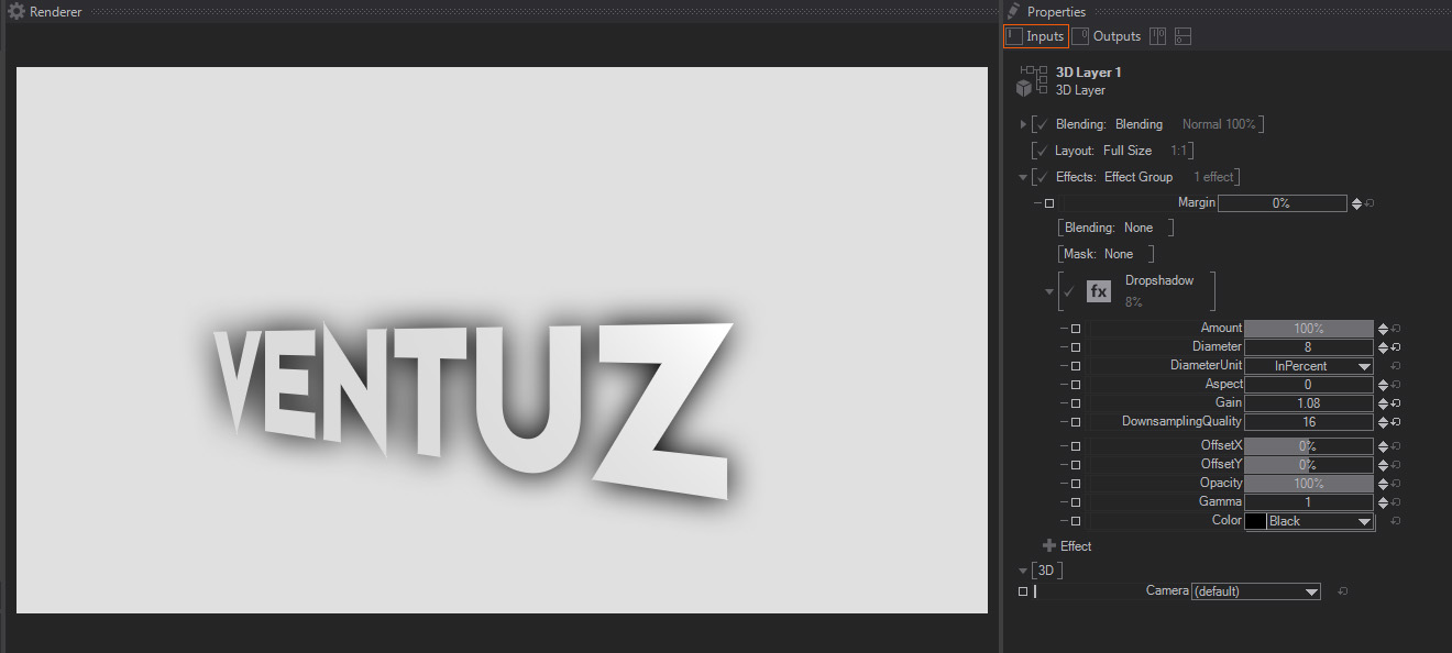
A Drop Shadow effect that generates a 2D shadow effect based on the Layer Alpha. It uses the same computation internally as the Blur effect and the Shadow can be tinted into colors other than Black. Apart from pure drop shadows, the effect can be used for many other effects, such as to create object glow effects (with light color settings) or outline effects (with a very small diameter setting). It features these parameters:
- Amount: A slider to control the strength of the Drop Shadow effect. The default 100% value means that the Drop Shadow will be exactly as generated by the rest of the parameters available. Lower values will divide the other Drop Shadow parameters, meaning that lower values will result in dimmed version of the Drop Shadow – this is great for animating the Drop Shadow effect as a whole.
- Diameter: A slider to control the Drop Shadow blur diameter, this diameter controls the Shadow spread or size as well. It uses the same computing method used for Blur, so it behaves exactly the same. The default value is 5.
- Diameter Unit: A dropdown menu that affects some of the other parameters (Diameter/Aspect and Downsampling), by setting the units used to calculate over what range the image is blurred.
The available values are “In Percent” -the default one, using percentage of the whole image size, or “In Pixels” – using absolute pixel values.
- Aspect: A slider to control the aspect ratio of the Drop Shadow diameter, so that it operates independently on the X and Y axis. Negative values will increase the Drop Shadow blur and deform the Shadow in the Y axis, while positive values will stretch and blur the Drop Shadow in the X axis.
- Gain: One slider which performs a Gain color correction in the shadow Alpha channel, therefore it enhances the shadow effect, making it harsher and more contrasted, regardless of the Shadow color. The default value is 1.
- Downsampling Quality: A slider which controls the downsampling, in order to improve performance, the system creates a downsampled proxy before blurring the Drop Shadow effect. The default value is 20.
The higher the values, the less downsampling occurs. With higher values the result will have better quality, but it will take more computation time to generate the Drop Shadow effect. So, in general, it is always good to keep it as low as possible to get results that are as good looking as needed without affecting your scene performance.
As a side note, this downsampling control also performs some filter permutation under the hood, so that explains why some values, the lower ones in particular, cancreate some image artifacts. - Offset X/Y: Two sliders to control the Shadow offset from the original layer Alpha. They allow controlling Offset in both X and Y individually. The Offset is expressed as percentage of total image size, and their default values are 0%.
- Opacity: One slider to control the Shadow opacity, to some extent it works exactly the opposite as the Gain control above, it dims the Shadow opacity. It is expressed as percentage of total opacity, and the default value is 100%.
- Gamma: One slider to control the Shadow relative contrast, this means that it is performing a Gamma color correction in the generated Shadow Alpha channel, making the shadow more or less contrasted. The default value is 1.
- Color: A dropdown menu to choose the color to be applied for tinting the Shadow. The default value is Black.
K1/K2 Lens Distortion
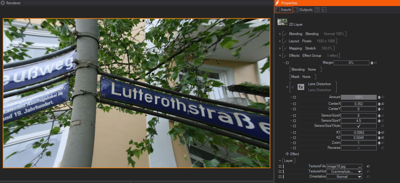
This distortion effect replicates the typical Barrel and Pin Cushion aberrations associated with optical lenses. It is based on the same maths used for Lens calibration in virtual workflows, and therefore it includes controls for the sensor size, zoom and the like. The parameters available are:
- Amount: A slider to control the strength of the Distortion effect. The default 100% value means that the Distortion will be exactly as generated by the rest of the parameters available. Lower values will divide the other Distortion parameters, meaning that the image channels will be less distorted – this is great for animating the Distortion effect as a whole.
- Center X/Y: Two sliders to move the center of the Lens for the Deformation calculation, in both X and Y axis individually. The units are expressed as Float, and the default values are 0.
- Sensor Size Size X/Y: Two sliders to enter the size of the sensor used by the Lens Deformation algorithm, in both X and Y axis individually. The units are Float and expressed as Millimeters, and the default values are 8 for Sensor X and 4.5 for Sensor Y.
- Sensor Size Y Auto: One Toggle that controls whether the CCD or sensor relative proportions are maintained or not, it overwrites the Sensor Size Y parameter above. The default value is On.
- K1: One slider to control the Pin-Cushion / Barrel deformation effect, with positive values performing a Pin Cushion deformation, while negative values produce a Barrel-like deformation. This one is more subtle than the K2 parameter below, units are Float and the default value is 0.
- K2: One slider to control the Pin-Cushion / Barrel deformation effect, with positive values performing a Pin Cushion deformation, while negative values produce a Barrel-like deformation. This one is more aggressive than the K1 parameter above, units are Float and the default value is 0.
- Zoom: One slider to control the emulate the Zoom control of the Lens model replicated for the Deformation calculation. Units are Float and the default value is 0.
Rational Lens Distortion
Like the K1/K2 Lens Distortion, this effect can apply or rectify lens aberrations. Unlike the K1/K2 distortion, this distortion uses a rational polynomial with up to 8 parameters: N1-4 for the nominator and D1-4 for the denominator. This allows for more precise lens calibration.
Distortion
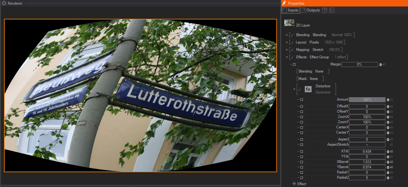
This distortion effect combines many of the distortion effect parameters, including some Barrel, Tilting, Polar/ radial deformations, etc. You can use it as your main deformation effect, unless you need some of the options available in more specific Deformation effects. The parameters available are:
- Amount: A slider to control the strength of the Distortion effect. The default 100% value means that the Distortion will be exactly as generated by the rest of the parameters available. Smaller values will divide the other Distortion parameters, meaning that the image channels will be less distorted – this is great for animating the Distortion effect as a whole.
- Offset X/Y: Two sliders to control the original image or layer offset but keeping the deformation matrix on the original position. They control the Offset in both X and Y individually. The Offset is expressed as percentage of total image size, and their default values are 0%.
- Zoom X/Y: Two sliders to control the distorted image size on the X and Y axis individually. The values are expressed in percentage of the total Image or Layer resolution, and their default values are 100%.
- Center X/Y: Two sliders to move the center of the matrix used for Deformation calculation, in both X and Y axis individually. The units are expressed as Float, and the default values are 0.
- Aspect: One slider to control the Aspect ratio or proportions of the Distortion. It combines with the Aspect Stretch setting below, which acts as a multiplier to this parameter values, meaning that if Aspect Stretch is On, the Aspect values will be modified to try to follow the layer aspect ratio. The units are expressed as Float, and the default value is 0.
- Aspect Stretch: One toggle to activate Stretching to the Image proportions or aspect ratio. This setting forces the Distortion effect to have the same aspect ratio as the original image. The default value is Off.
- X Tilt: One slider to control Tilting or Skewing Distortion, like pulling from the top and the bottom edges of the image in two opposite directions, along the X axis. The units are expressed as Float, and the default value is 0.
- Y Tilt: One slider to control Tilting or Skewing Distortion, like pulling from the left and the right edges of the image in two opposite directions, along the Y axis. The units are expressed as Float, and the default value is 0.
- X Barrel: One slider to control Barrel Distortion on the X axis, like shrinking from the top and the bottom edges of the image while keeping the central areas mostly not deformed. The units are expressed as Float, and the default value is 0.
- Y Barrel: One slider to control Barrel Distortion on the Y axis, like shrinking from the left and the right edges of the image while keeping the central areas mostly not deformed. The units are expressed as Float, and the default value is 0.
- Radial 1: One slider to control Radial Distortion, often called Bulge deformation. The image pixels are more deformed the closer they are to the Center set by Center X and Y parameters above, while pixels are less deformed the further away from the center they are. The units are expressed as Float, and the default value is 0.
- Radial 2: One slider to control Radial Distortion, often called Bulge deformation. It is very similar to Radial 1 above, but results are slightly different. The units are expressed as Float, and the default value is 0.
RGB Distortion
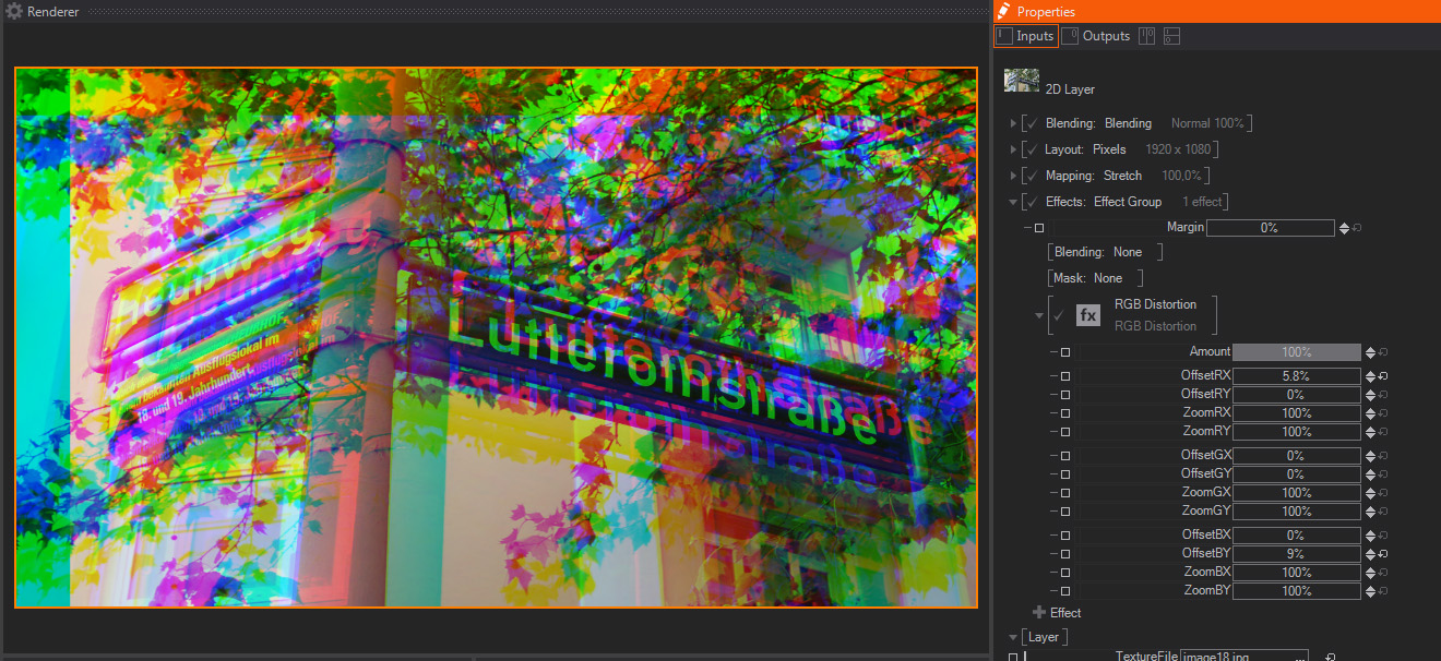
This is commonly called a Twitch effect, it offsets and scales the Image or Layer Red, Green and Blue channels spatially, so R, G and B pixels are not aligned or they have different sizes.
- Amount: A slider to control the strength of the Distortion effect. The default 100% value means that the Distortion will be exactly as generated by the rest of the parameters available. Smaller values will divide the other Distortion parameters, meaning that the image channels will be less distorted – this is great for animating the Drop Shadow effect as a whole.
- OffsetR X/Y: Two sliders to control the Red channel offset on the X and Y axis individually. The values are expressed in percentage of the total Image or Layer resolution, and their default values are 0%.
- ZoomR X/Y: Two sliders to control the Red channel size on the X and Y axis individually. The values are expressed in percentage of the total Image or Layer resolution, and their default values are 100%.
- OffsetG X/Y: Two sliders to control the Green channel offset on the X and Y axis individually. The values are expressed in percentage of the total Image or Layer resolution, and their default values are 0%.
- ZoomG X/Y: Two sliders to control the Green channel size on the X and Y axis individually. The values are expressed in percentage of the total Image or Layer resolution, and their default values are 100%.
- OffsetB X/Y: Two sliders to control the Blue channel offset on the X and Y axis individually. The values are expressed in percentage of the total Image or Layer resolution, and their default values are 0%.
- ZoomB X/Y: Two sliders to control the Blue channel size on the X and Y axis individually. The values are expressed in percentage of the total Image or Layer resolution, and their default values are 100%.
2D Displacement
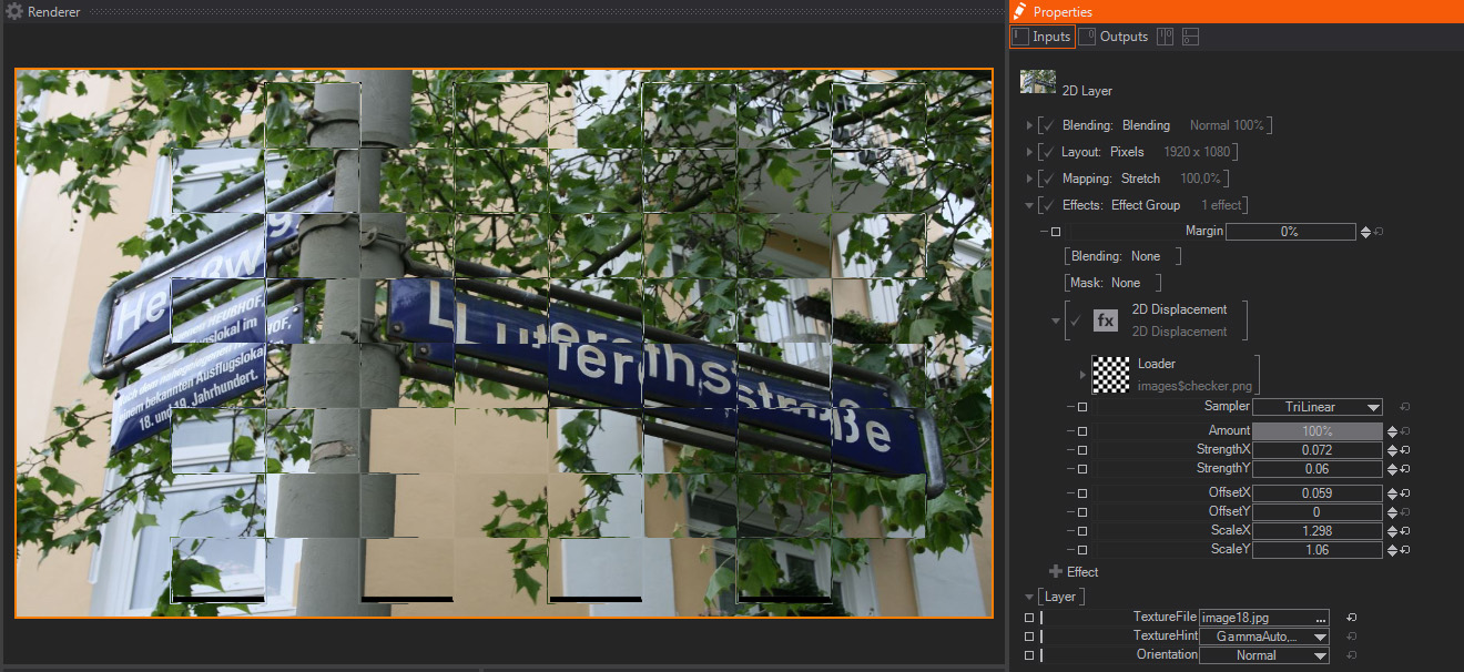
A standard 2D displacement effect, it displaces the Image or Layer pixels according to the Luminance information of an external image or Movie file. Due to this, it is always a good idea to use a very contrasted image to see the effect to its full strength. Generally a Black Texture will move the pixels to the top left while a white texture will move them to the bottom right.
- Loader: It loads an external file, which will be used as the displacement information source. By default it loads an internal checkerboard image, as shown on the Loader Thumbnail and in File property, which shows the image file path.
If we expand the Loader property a new File option appears, showing the complete path of the Image file.
In addition, if we click on the little arrow close to the Loader, it only appears when we place our mouse cursor on this area, another contextual menu appears. This new menu shows Loader presets and additional options, like:
- Loader: This preset shows a list of internally available files which could be used as Displacement Maps. These images are installed with Ventuz installer by default, so they are available for all users and projects. The available options are:
- Checker
- Checker Blue
- Checker Dots
- Lines
- Dimple
- Liquid
- Noise
- Texture Property:
- Empty
- Movie Clip
- Movie Frame
- Movie Stream
- Live Video
- Texture Loader
- Sampler: One Dropdown menu to pick up how pixels will behave when reaching the image limits - in other words, if areas outside the image limits will be black, repeat the image pixels, mirror them, and so on. It also allows selecting what kind of spatial filtering will be used for these transformations.
The upper part of the drop down menus selects the filter used for the mask transformations, scaling in particular.
The lower part of the drop down menu features how the image file is tiled if the mask image doesn´t cover the whole Layer area. In other words, it controls if the mask image is repeated and how.
Two options can be selected in the dropdown menu to control the transformations filter and how the image is tiled individually.
- Tri-Linear Filter: A check box to connect or disconnect this filtering option.
- Black: The pixels outside the area covered by the mask are turned black, meaning that there is no tiling.
- White: The pixels outside the area covered by the mask are turned white, meaning that the area outside the original mask image is totally opaque.
- Clamp: The pixels outside the area covered by the mask will repeat endlessly the same values as the pixels in the original image borders.
- Wrap: The pixels outside the area covered by the mask are repeated or tiled as they were in the original mask image.
- Mirror: The pixels outside the area covered by the mask are repeated or tiled as they were in the original mask image, but inverted, like a mirror effect, hence the name.
- Tri-Linear Filter: A check box to connect or disconnect this filtering option.
- Flags: The Flags property allows for some options:
- Mapping Relative: Maps the Texture Input with the Range [0,1] to a relative displacement of [-1,+1]
- Mapping Absolute: Maps each pixel to the position defined in the texture regardless of its original position.
- Amount: A slider to control the influence of the Displacement effect. The default 100% value means that the Displacement will be exactly as generated by the rest of the parameters available. Smaller values will divide the other Displacement parameters, meaning that the image pixels will be less displaced – this is great for animating the Drop Shadow effect as a whole.
- Strength X/Y: Two sliders to control how much the Image or Layer pixels will be displaced on X and Y axis individually.
Pixels are always displaced in the same axis, but into opposite directions at the same time, meaning that some will be moved to the X axis positive values, while some others will be moved towards the X axis negative values. Strength negative values will swap displacement directions. The same happens on the Y axis as well. The values are expressed as Float, and their default values are 0. - Offset X/Y: Two sliders to translate the external image used as Displacement map on the X and Y axis individually. The values are expressed as Float, and their default values are 0.
- Size X/Y: Two sliders to scale the external image used as Displacement map on the X and Y axis individually. The values are expressed as Float, and their default values are 1.
Noise Distortion
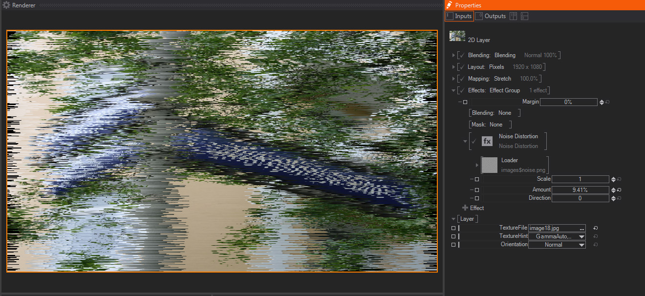
This effect is very similar to the 2D Displacement effect above, but the external Image file is randomly animated to create a fake Noise Displacement effect. It features less and simpler controls than 2D Displacement, the available parameters are:
- Loader: It loads an external file, which will be used as the displacement information source. By default it loads an internal checkerboard image, as shown on the Loader Thumbnail and in File property, which shows the image file path.
If we expand the Loader property a new File option appears, showing the complete path of the Image file.
In addition, if we click on the little arrow close to the Loader, it only appears when we place our mouse cursor on this area, another contextual menu appears. This new menu shows Loader presets and additional options, like:
- Loader: This preset shows a list of internally available files which could be used as Displacement Maps. These images are installed with Ventuz installer by default, so they are available for all users and projects. The available options are:
- Checker
- Checker Blue
- Checker Dots
- Lines
- Dimple
- Liquid
- Noise
- Texture Property:
- Empty
- Movie Clip
- Movie Frame
- Movie Stream
- Live Video
- Texture Loader
- Scale: One slider to control the external Displacement Map size, which is scaled according to this parameter value. The units are expressed as Float, and the default value is 1.
- Amount: One slider to control the strength of the Displacement effect, as opposed to the 2D Displacement, it works both for X and Y axis. The units are expressed as percentage of total image size, and the default value is 100%.
- Direction: One slider to rotate the Displacement axis orientation. The units are expressed as Degrees, and the default value is 0.
Polar Distortion
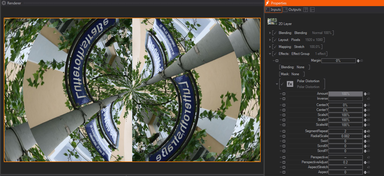
Polar Distortion is a distortion effect that transposes the x and Y pixel coordinates in the original image to a Polar Coordinate system, which is similar to the Longitude and latitude coordinate system used for Geographical positioning. As a result of this transpose conversion, the resulting images are heavily distorted, offering some very interesting results. These are the parameters available:
- Amount: A slider to control the strength of the Polar Distortion effect. The default 100% value means that the Polar Distortion will be exactly as generated by the rest of the parameters available. Smaller values will divide the other Polar Distortion parameters, meaning that smaller values will interpolate between the original image and the Polar Distortion effect– this is great for animating the Polar Distortion effect as a whole.
- Inverse: One toggle to control which coordinate system conversion is applied. If the default Off value is selected the effect will convert from standard Cartesian X,Y to Polar coordinate system, like the "Rect to Polar" setting in other software packages in the market. On the contrary, if the value is On, the conversion will be from Polar to Cartesian X,Y coordinate system, what's known as "Polar to Rect" in other software packages.
- Center X/Y: Two sliders to move the center of the Polar Distortion effect calculation in both X and Y axis individually. The units are expressed as Percentage of total Image resolution, and the default values are 0%.
- Scale X/Y: Two sliders to scale the Polar Distortion effect calculation in both X and Y axis individually. The units are expressed as Percentage of total Image resolution, and the default values are 100%.
- Scale All: One slider to scale the Polar Distortion effect as a whole, in both X and Y at once. The units are expressed as Percentage of total Image resolution, and the default value is 100%.
- Segments: One slider to control the amount of segments iterations created. The units are expressed as Float, and the default value is 5.
- Radial Scale: One slider to scale the result according to the Polar coordinate system. The units are expressed as Float, and the default value is 1, with higher values stretching pixel positions in polar directions from the Center location, while smaller values will shrink towards the center location, following the Polar coordinates direction.
- Swirl: One slider to deform the Polar Distortion as a spiral, in other words, the higher the values, the more complex the spiral created by the Polar Distortion - negative values work the same, just turning the spiral in the opposite direction. The units are expressed as Float, and the default value is 0.
- Scroll X/Y: Two sliders to move the Polar Distortion segments radially in the polar X and Y axis individually. The units are expressed as Float, and the default values are 0 for both controls.
- Perspective: One toggle to activate the Perspective calculation. This Perspective setting forces the Polar Distortion effect to try to mimic a fake perspective - it is useful to simulate Tunnel-like effects. The default value is Off.
- Perspective Adjust: One slider to control the Perspective calculation, therefore it works in combination with the Perspective setting above, which must be On in order to use this parameter. The units are expressed as Float, and the default value is 0.2.
- Aspect Stretch: One toggle to activate Stretching to the Image proportions or aspect ratio. This setting forces the Kaleidoscope effect to have the same aspect ratio as the original image. The default value is Off.
- Aspect: One slider to control the Aspect ratio or proportions of the Polar Distortion. It combines with the Aspect Stretch setting above, which acts as a multiplier to this parameter values, meaning that if Aspect Stretch is On, the Aspect values will be modified to try to follow the layer aspect ratio. The units are expressed as Float, and the default value is 0.
Kaleidoscope Distortion
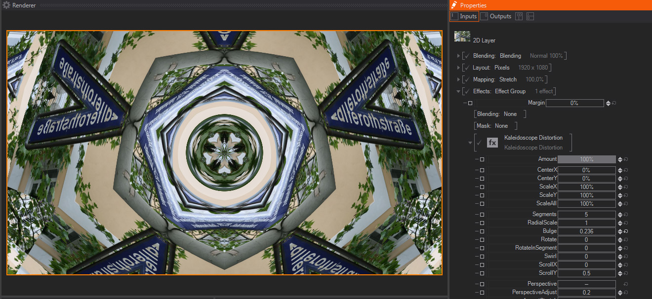
- Amount: A slider to control the strength of the Kaleidoscope effect. The default 100% value means that the Kaleidoscope will be exactly as generated by the rest of the parameters available. Smaller values will divide the other Kaleidoscope parameters, meaning that smaller values will interpolate between the original image and the Kaleidoscope effect– this is great for animating the Kaleidoscope effect as a whole.
- Center X/Y: Two sliders to move the center of the Kaleidoscope effect calculation in both X and Y axis individually. The units are expressed as Percentage of total Image resolution, and the default values are 0%.
- Scale X/Y: Two sliders to scale the Kaleidoscope effect calculation in both X and Y axis individually. The units are expressed as Percentage of total Image resolution, and the default values are 100%.
- Scale All: One slider to scale the Kaleidoscope effect as a whole, in both X and Y at once. The units are expressed as Percentage of total Image resolution, and the default value is 100%.
- Segments: One slider to control the Kaleidoscope segments, meaning the number of instances of the original image created internally and duplicated along the polar coordinates. The units are expressed as Float, and the default value is 5.
- Radial Scale: One slider to scale the Kaleidoscope number of segments in the radial direction, meaning the quantity of segment levels to create the final kaleidoscope effect. The units are expressed as Float, and the default value is 0.
- Bulge: One slider to create a Bulge deformation at the center of the Kaleidoscope, meaning that kaleidoscope will be distorted radially from the center, new level will be generated according to the new values. The units are expressed as Float, and the default value is 1, with negative values expanding the center deformation and positive values compressing to the deformation center.
- Rotate: One slider to rotate the Kaleidoscope as a whole. The units are expressed as Float, and the default value is 0.
- Rotate in Segments: One slider to rotate Kaleidoscope individually, in other words, each segment will be rotated around its own rotation center. The units are expressed as Float, and the default value is 0.
- Swirl: One slider to deform the Kaleidoscope as a spiral, in other words, the higher the values, the more complex the spiral created by the Kaleidoscope - negative values work the same, just turning the spiral in the opposite direction. The units are expressed as Float, and the default value is 0.
- Scroll X/Y: Two sliders to move the Kaleidoscope segments radially in the polar X and Y axis individually. The units are expressed as Float, and the default value for Scroll X is 0, and for Scroll Y is 0.5.
- Perspective: One toggle to activate the Perspective calculation. This Perspective setting forces the Kaleidoscope effect to try to mimic a fake perspective - it is useful to simulate Tunnel-like effects. The default value is Off.
- Perspective Adjust: One slider to control the Perspective calculation, therefore it works in combination with the Perspective setting above, which must be On in order to use this parameter. The units are expressed as Float, and the default value is 0.
- Aspect Stretch: One toggle to activate Stretching to the Image proportions or aspect ratio. This setting forces the Kaleidoscope effect to have the same aspect ratio as the original image. The default value is Off.
- Aspect: One slider to control the Aspect ratio or proportions of the Kaleidosope. It combines with the Aspect Stretch setting above, which acts as a multiplier to this parameter values, meaning that if Aspect Stretch is On, the Aspect values will be modified to try to follow the layer aspect ratio. The units are expressed as Float, and the default value is 0.